N55 ROCKET SYSTEM

N55 ROCKET SYSTEM, Copenhagen, Denmark, 2005
Introduction:
The N55 ROCKET SYSTEM enables persons to communicate their protest in a concrete way. It is a low tech, low cost, highly efficient hybrid rocket propulsion system, fueled by a mixture of polyethylene and laughing gas (N2O).
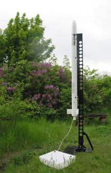
The N55 ROCKET SYSTEM makes it possible to distribute various things from high altitudes. For example, printed matter or plant seeds could be spread over a vast area.The rocket PROTEST, constructed to protest against large concentrations of power, can carry a payload of 2 kg to an altitude of approximately 5200 m, if launched from an angle of 85 degrees. The fuel will burn for 6 seconds, bringing the rocket to a maximum speed of 475 m/s. The N55 ROCKET SYSTEM has been equipped with a parachute and can be reused when a mission is completed. The ROCKET SYSTEM is part of the N55 SPACE PROGRAMME, which aims at creating space for persons and making space technology accessible and useful in everyday life situations.
Political background:
Big corporations increasingly decide over and profit on vast dominions of human existence. Formerly common things such as land, water, the air (the rights to pollute) are being monopolised. Food is being polluted by GMOs introduced without any public knowledge. The traditional means of protesting through street manifestations and via formal channels seem inadequate for invoking changes in the present dangerous and undemocratic situation. As people in power fail to live up to their social responsibilities, and let populations down by favouring concentrations of power, the need for new means of expression emerges.
Relatively advanced technology is normally only available to concentrations of power such as governments or corporations, or a few highly specialised individuals. The N55 SPACE PROGRAMME, and the N55 ROCKET SYSTEM, is part of an effort to distribute and give persons in general access to specialised knowledge and technology.
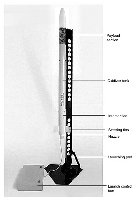
PROTEST with launching pad and launch control box.
Payload:
The version of PROTEST shown in this manual carries a payload of ‘Superweeds’: seeds of naturally occuring and genetically modified (GM) weed plants that if allowed to germinate and crosspollinate, will evolve into a Superweed that will be resistant to current herbicides such as Roundup. To counter the threat of genetic pollution posed by biotech firms, persons are encouraged to equip themselves with superweeds to potentially sabotage commercial GM crop fields. SuperWeeds are distributed by Heath Bunting, http://www.irational.org/cta/superweed/
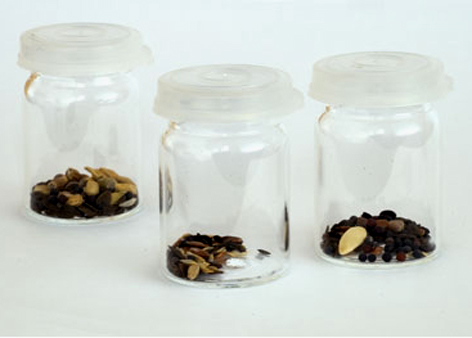
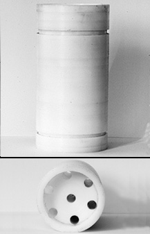
Payload: Capsules with superweeds will be released once the rocket reaches its peak
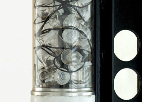
Payload:
The blasting bolt fixed at the center
of the payload section is controlled by a timer. The blast will cause
the rocket to divide into two parts
A parachute will unfold and bring the rocket parts undamaged to the ground.
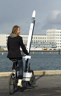 ROCKET SYSTEM, mounted on bike, 2005 |
 |
Technical background:
There exist three forms of chemical rocket engines, defined by the form of their propellants: solid, liquid, and hybrid propellants. The first and most simple form uses a mixture of rubbery fuels mixed with crystalline oxidizers and often powdered metals like aluminium are used to increase the energy content. In the solid rocket motor a so-called ‘grain’ made of this fuel is burned slowly to produce hot gasses under high pressure. The solid rocket is simple, but unfortunately it cannot be stopped once ignited � and the propellants are potential explosives that must be manufactured under rigorous safety precautions. Examples of use are most military missiles, and strap-on boosters like the SRB´s or solid rocket boosters used on the space shuttle.
Liquid propellant rocket engines are typified by high performance, high versatility and a complex design. Unlike solid motors they can be stopped and started many times and can be designed for reuse and multiple starts and stops. A liquid propellant rocket motor may also be throttled during flight. The drawback of liquid rocket propul-sion lies in the complexity of the engine, fuel and oxidizer surplus systems (that may include turbo pumps) and the resulting high cost. Liquid propellants may be corrosive and toxic chemicals, especially if they are to be earth storable. Examples of use are in most spaceboosters e.g. the space shuttles’ main engines and in most manned rocket applications.
Hybrid rockets are essentially designed to combine the best from both forms of rocket propulsion. The fuel will be a polymer like polyethylene LDPE or hydroxyterminaltedpolybutadien HTPB, and the oxidizer either liquid oxygen, LOX or dinitrogenoxide, N2O (laughing gas). The solid fuel is placed in a combustion chamber. It is machined or cast into a desirable form, most often with one or more longitudinal openings or ports. Combustion takes place in these ports when oxidizer liquids are sprayed over the top of the polymer fuel block. Downstream the fuel, just above the nozzle, the combustion completes and as in any rocket, hot gasses under high pressure is formed. This gas is then expelled through the nozzle where the gas reaches speeds in the 1500 - 3000 m/s range.
What makes a hybrid rocket very interesting is the safe, simple and cheap design. A solid propellant rocket may explode violently if a crack appears in the fuel grain. A liquid engine may explode e.g. during start if fuel and oxidizer liquids are mixed but not ignited until some mass of the mixture has accumulated. This most often starts a cataclysmic destruction of the entire rocket system and its cargo or crew. In conventional rockets these explosions occur when the design fails to control the rate by which propellants are burned and turned into hot high pressure gasses.
In a hybrid rocket the solid fuel and liquid oxidizer cannot be mixed any faster than the solid can be evaporated into combustible gasses. As a result the system is potentially much safer than any of the two first type of rockets. Most important hybrids still can be turned on and off, and even throttled by changing the flow of oxidizer.
In the practical world the liquid oxidizer must still be fed to the combustion chamber. This can be done using pumps or pressurized tanks. The most weight economic method depends on the size of the system and of the material that the tanks and combustion chamber are made from. Today ultra high strength synthetic fibres like glass, kevlar or carbon fibre are commonly available along with epoxy binders, so only in the most extreme size of rockets will the turbopump systems be superior. For low-tech simple systems, ordinary steels or stainless steel are quite suitable and very robust materials.
The oxidizer used for the N55
ROCKET SYSTEM is dinitrogenoxide (N20). It is chosen for availability
and safety. It is purchased in steel cylinders under pressure and can
be fed under pressure to the rocket’s flight tank. At 20 deg. C the
steam pressure of N20 is some 40 bars, quite adequate for supplying it
to the combustion chamber. All parts of the rocket are made of steel,
copper and fiberglass, are machined using simple machinery and subsequently
TIG welded.
Oxidizer tank:
The oxidizer tank is the largest and most heavy part of the hybrid motor. Its stores the N20 oxidizer at very high pressure, and must be made with great care, since failure of the tank during filling and pressure rise is the most dangerous process during preparation of the rocket.
The tank is made from mild steel tube. The tube is cut to length, and is fitted with a forward and aft bulkhead. The bulkheads are turned into a section of a sphere to increase strength. This is done using a hydraulic press. Such endcaps can also be purchased, but with a hydraulic jack and a short section of the tank skin it can be made much cheaper.
At the center of both endcaps holes are cut for the main oxidizer valve and for the filling valve. Finally a skirt is welded on both ends to make it possible to connect the tank to the other section of the rocket.
Possible improvements of the tank:
The problem with the tank is the mass of it. Improvements must aim at reducing weight. This can be done in a number of ways. Reducing the very high margins of safety of the present rocket “PROTEST” is one potentially dangerous way. Instead it would be cheap and simple to give the tank a carbonfibre unidirectional “coil” – simply wrapping it into a coil of carbon fibre to transfer radial forces from the steel to a much stronger fibre material. In a perfect design, only longitudinal forces would be absorbed by the inner steel tank. Relative to “PROTEST” this could take some 50 % of the weight away. It preserves the simple connections made in welded steel, and would have great effect in a slightly larger rocket.
To make the entire tank from
carbon fibre would reduce 80 – 95 % of the weight of the tank body,
but valves and connections would be a relatively great weight expense.
Intersection:
The section leading to the combustion chamber holds the main valve. The
valve is remotely operated from the PROTEST launch control box. The actuator
is placed on the launcher, and connects to the valve shaft with a clutch.
This clutch automatically disconnects at blast off. Once in the air the
valve remains open and N20 oxidizer flows to the combustion chamber.
In a slightly larger rocket the valve can be radio controlled, and have its actuator onboard. This allows for in-flight premature cut-off – restart and throttling.
Injector:
The N20 oxidizer injector is machined from mild steel. It meters and controls the flow of the oxidizer. The six 1.5 mm oxidizer holes are angled to induce impingement leading to effective atomisation of the oxidizer. The complex two-phase flow of N20 cannot be predicted by standard injector calculations, so test using actual N20 is needed to understand the process. Extensive testing have indicated that a hole of 1 mm ( area 0.78 mm2 ) injects some 0.050 kg N20 pr. sec, and this figure being almost unaffected by the pressure drop. The ‘PROTEST’ injector has six 1.5 mm holes, and its designed to inject some 0.650 kg of N20 pr sec.
Possible improvements of the injector:
In a slightly larger system a more complex injector can be used to induce better atomisation, possibly surpressing combustion instability and motor vibration.
Ignition system:
The ignition of a hybrid motor is simpler than one would expect. In the ‘PROTEST’ motor a pyrotechnic strand burner is inserted from one side and a pyrotechnic scuip or igniter is inserted from the other.The openings are placed just downstream of the injector above the fuel grain. Prior to launch, at T-5 sec, the pyrotechnic device is activated. Its combustion fills the combustion chamber with reducing gases and decomposing plastic fuel gases. Once the main valve is opened the gases mix, react and release more fuel gases from the plastic fuel – and the motor is on.
Improvements of the ignition system:
None. During years of testing the ignition system has never failed.
Fuel grain:
The fuel for ‘PROTEST’ is polyethylene. Combustion of this material is clean, efficient and predictable. The gases produced are mainly carbonoxide, carbondioxide and water. The mixture of 02 and fuel gases starts at the top, and as the hot gases flow down the seven ports of the grain more and more fuel is induced to the mix. The length to diameter ratio of the ports determine the fuel to oxidizer mixture ratio. As the ports gradually open the combustion rate reduces, and this compensates to some extent for the change in O/F ratio. Still there are some changes, starting with a relatively fuel rich mixture that gradually goes closer to neutral. However the N20 / HDPE combination is very insensitive to this change, exhaust speed vary some less than 10 % from a mixture ratio of 5 to a mixture ratio of 10 kg N20 / kg fuel.
The fuel grain is placed in the combustion chamber and is sealed to the chamber walls with two o-ring seals. These prevent combustion on the outside of the grain by stopping the flow of N20 here. Close to engine cut off these O-rings are no longer needed, and they partially burn with the rest of the fuel.
Possible improvements to the fuel grain:
‘PROTEST’ uses a grain with seven cylindrical ports. The fuel residue can be reduced using a more complex configuration, but the gain is limited. Other improvements could be finding the perfect length to produce gases with non-oxidizing properties
Combustion chamber:
The combustion chamber is made from the same type of tube as the oxidizer tank. It is not directly exposed to hot gases, but some heat transfer must be expected at the top, and near the nozzle. Because of the large (15 – 20 bar) injector pressure drop the combustion chamber is not as highly stressed as the tank. The fuel grain is inserted during fabrication and the combustion chamber is welded outside the grain.
Possible improvements:
Same as the oxidizer tank,
but less important. Secondary would be anything that could make the gasses
produced in the combustion chamber non-oxidizing.
 Steering fins and nozzle |
 Fuel grain |
Nozzle:
In the De Laval nozzle of the ‘PROTEST’, the heat and pressure energy of the combustion products are converted into kinetic energy. In fact the purpose of the whole motor system is to supply the nozzle with hot gasses under high pressure. The nozzle is under very high heat stress, and also exposed to some chemical oxidizing stress. Due to the sometimes oxidizing properties of the medium, nozzles made from graphite and carbon may have very high regression rates. For this reason and for its ability for reuse, the ‘PROTEST’ nozzle is made from cupper.
Technical specifications:
Maximum speed: approx. 475
m/s or 2600 km/h
Apogee: 5200 meters at a launch angle of 85 degrees
Net weight: 8,5 kg
Fuel weight: 3.8 kg
Component list:
Steel tube Ø 102 mm
Acrylic tube Ø 100 mm
Rocket head: Fiberglass / epoxy
Cupper nozzle
Parachute
Fuel grain: LPDE polyethylene block
Oxidizer: N20
Bolts, nuts
Launching pad
Launch Control Box:
Polyethylene box, electric cords, electric switches
N55 ROCKET SYSTEM situations:
N55 ROCKET SYSTEM, Copenhagen, Denmark, 2005

N55
ROCKET SYSTEM, Gothenburg, Sweden, 2005

Kunstnernes hus, Oslo, Norway, 2005

By N55 in Collaboration with Peter Madsen