CLEAN AIR MACHINE
 CLEAN AIR MACHINE, 1997 |
 Component diagram |
Introduction:
The CLEAN AIR MACHINE enables persons to improve the air quality of their indoor environment. The CLEAN AIR MACHINE cleans the air of dust, viruses, fungus, bacteria, toxic gases, malodorous gases, organic solvents, smog, carbon monoxide etc This version of the system is dimensioned for cleaning 600 m? per hour, which corresponds to an area of approximately 120 m� The capacity and efficiency can be increased and the system can be extended with functions such as air humidifying, cooling and heating. The machine can be installed separately as a mobile unit or be permanently incorporated in a building and connected to ventilation ducts distributing the clean air to the entire building.
Technical background:
The CLEAN AIR MACHINE takes into account all known sources of air pollution.
Air is sucked into the CLEAN AIR MACHINE by a ventilator and passes through a row of filters capable of both chemical and mechanical cleaning. The cleaned air is then circulated back into the room. The filters are put together in such a way that they ensure an optimum efficiency and long life of the device.
System components:
In order to achieve the high purity of the treated air the following components are used:
Prefilter
A washable PE-prefilter is mounted at the air intake. This filter holds back the biggest dust particles and keeps the ventilator and the sound absorption system from becoming dirty. In addition it increases the life span of the activated carbon filter and the protective filter.
Sound absorption
The protective filter and the HEPA filter demand high air pressure, causing air noise. This is eliminated with a sound absorption system mounted at the air intake and at the air outlet.
Ventilator
The only usable ventilator is a centrifugal type given the required final air pressure of approx. 500 pa. The one chosen here maintains this pressure at an airflow of 600 m?/h. An RPM (rotations per minute) regulator is mounted in order for the final air speed and pressure to be adjusted manually.
Activated carbon (AC) filter
In order to remove molecular particles such as fine smoke, malodorous and toxic gases, organic compounds, ozone etc. from the air, a very effective active carbon filter is installed. The carbon is put into a bag, which makes changing easy when the carbon is no longer effective. The life time of the carbon varies greatly depending on the local environment.
Protective filter
The most expensive component, and one that needs periodic change, is the HEPA filter. In order to increase the interval between the changes installation of a protective pre-filter is necessary. The filter chosen should ensure the HEPA filter a lifetime of approx. 5 years.
Sterile filter
The sterile filter, or the HEPA filter, is accessible in different degrees of fineness. It is important to evaluate price, life span and pressure loss with the achieved degree of filtration. This filter has the classification EU 13 which has an efficiency of 99.997% at 0.3 nm particle sizes, which ought to be satisfying in most cases.
UVC system
A UVC lamp is built into the system to deactivate viruses and other micro- organisms that are not held back in the HEPA filter This is to eliminate air-born infectious diseases like influenza and the common cold. The radiation dose is calculated according to an air speed of 600 m?/h, and the efficiency will increase at a lower air speed.
Electricity
The CLEAN AIR MACHINE is constructed for connection to 230 V AC. If it is aimed at instalment in a channel system, three-phase current will be more appropriate.
Extra equipment:
Extra equipment may be added in order to increase the system's efficiency, and the air cleaning may be combined with different comfort functions: Even though smog and other gases are removed in the activated carbon filter there might, if the system is to work optimally, be a need for catalytic oxidation. This is achieved with UVC-activated titanium dioxide.
By adding an ozone generator a 100% sterile airflow will be guaranteed. Furthermore, one or two electric heating cartridges can be installed to regulate the temperature of the air, thus the airflow will be less noticeable. An air humidifier and/or an air dehumidifier can be installed. Finally an exhaust fitting can be mounted in order to steer the direction of the air flow over an angle of +/-45°.
Technical specifications and maintenance:
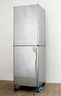
The components are built into two horizontally mounted cabinets that can be assembled and dismantled without tools. This means that it is easy to change filters and UVC tubes.
Present configuration:
Electricity consumption: Ventilator 410 W, UVC lamp 40 W = 450 W total, by normal operation (reduced ventilator speed) app. 200 W.
Dimensions: 650 x 650 x 2050 mm.
Transport weight: 80 kg.
| Components | Type | Dimensions | Efficiency | Change | Remarks |
| Prefilter | G80 Polyethylene | 610 x 610 x 20 | 57 % | washable | |
| Sound Absorption | Polyethergranulate | > 50% | - | 135 MK | |
| Ventilator | D2E 160-AB 01-06 | 270 x 206 x 204 | 500 pa. at 600 m3/h | - | 410 W |
| AC filter | BGP 8-16 | 610 x 610 x 50 | activated | 6 months | 2,5 l |
| Protective filter | Turbo-Flo F8566 | 610 x 610 x 300 | 46 % | 1 year | - |
| HEPA filter | EU 13 | 610 x 610 x 300 | 99,997 % at 0,3 nanom. particle size | 5 year | - |
| UVC lamp | TUV UVC 36 W | 420 x 38 | 16 W at 253,7 nm. | 1 year | - |
Component list:
Ventilator:
D2E 160-AB 01-06, 410W radial ventilator 1195 m?/h, 1850 revolutions/min.
Noise traps:
Sound absorbent recombined polyether granulate with open cells, 5 cm.
Cabinet:
1 mm stainless, acid-resistant steel (AISI 316 L).
Built-in boxes:
High density fiber plates, 10 mm.
1 pc washable PE pre-filter
1 pc activated carbon filter: 2.5 l activated carbon, type BGP 8-16
1 pc protective filter, polypropylene 30 cm
1 pc sterile filter: HEPA filter 13 EU
1 pc UVC - filter: 36 W TUV UVC tube
4 transport wheels, double rotational wheels, nylon and polyurethane
1 pc RPM controller
Various bolts and nuts.
Back to manuals
Back to HOME